Wiki Lab Writeup for Group 12b
TITLE HERE
Barrett Nibling, Travis Nokes, Kurt Strovink
November 19th, 2007
Contents |
Abstract
This experiment uses a video camera to record diffraction pattern intensity emitted by a He-Ne laser, which are then compared to theoretical single slit diffraction values. The error present in the measurements is less than ?%.
List of Figures
- Schematic of Diffration Apparatus
- Intensity of Diffraction Pattern
Introduction
This experiment examines the far field diffraction pattern for a laser through a single slit. Intensity on the screen is measured with a digital camera and associated software. The inclusion of a scale on the screen makes error in position measurements trivially small. To reduce error in intensity, two pictures are analyzed; one with the iris of the camera nearly shut to get an accurate reading at the main peak and a second with the iris open to allow more accurate examination of the fringes.
Theory
Single slit diffraction refers to the tendency for light to spread out after passing through a slit. The phenomenon can be understood through Huygens principle, which states that a wave front can be treated as a line of point sources. When such a wave front hits a slit, the smaller set of point sources produces an interference pattern. To predict the minima, it is fairly simple to show that if a point at one edge interferes destructively with a point in the center, an adjacent set of points will also interfere destructively, and the argument follows for the entire slit. The minima should therefore match the pattern produced by two narrow slits spaced at half the width of the slit. A more rigorous treatment predicts the following intensity pattern [1]:

|
![= I_0 {\left[ \operatorname{sin} \left( \frac{\pi a}{\lambda} \sin \theta \right) \right] }^2](/csm/wiki/images/math/a/6/9/a69ee07a2722b137122897d50501ae55.png)
|
where a is the slit width, λ is the wavelength, and θ is the angle from the normal to the slit.
Procedure
As shown below, a diffraction grating is placed in front of the helium-neon laser. The diffraction grating is positioned level with the light source and perpendicular to the axis of the beam. A viewing screen with a ruler mounted level with the emitted beam is placed directly in the path of this diffracted beam. A video camera is mounted, facing the viewing screen. The camera transmits the relative intensity of the diffraction pattern to the computer program.

Before data can be recorded, the ruler is photographed alongside the diffraction pattern to calibrate the horizontal scale. The viewing area is restricted to a single line through the center of the diffraction pattern and the lens iris is adjusted to prevent saturation. The viewing area is then expanded to encompass the entire diffraction pattern and reduce speckle pattern noise. These relative intensity measurements are observed and recorded.
Results
The following tables and graphs are the results acquired from the diffraction pattern recorded by the video camera.
The graph above shows results with the iris open to obtain a representation of the fringe pattern.
The following graph shows the results obtained with the iris nearly closed, yielding a clear representation of the intensity maxima in the center.
[edit] Error Analysis
For the error analysis, there variable associated with an error is θ.
The partial error for this variable is calculated from the formulas

and,
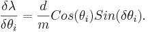
Then the total error is the sum of the two partial derivatives added in quadrature,
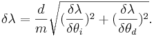
The values for δθd and δθi used are half the value of the smallest unit of measure on the device, .05 degrees.
Conclusion
Conclusion (Barrett)
References
[1] Wikipedia - Diffraction (online at http://en.wikipedia.org/wiki/Diffraction)